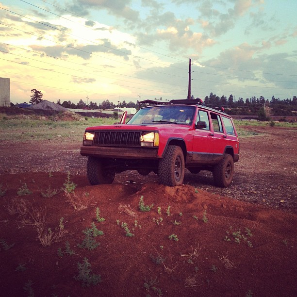
I built a 4 link rear suspension for my Jeep Grand Cherokee. To some, that’s not impressive at all. To others, it’s a really big deal. I’m of the mind that it’s a pretty big deal. There was a lot of math, measurements, and SO MANY STEPS, (not to mention that it’s definitely a critical system) that it may be my most proud accomplishment in the automotive world to date. And if I say so myself, it turned out good. Like, really good. I made some mistakes along the way, and I’ll share those of course. But before we get started, let’s talk about what a 4 link is, and why I chose it.
A double triangulated 4-link setup. Courtesy 1972CJ5+1 on Pirate4x4.com
There are a TON of rear suspension options out there. I encourage you to do your own research here, because there is SO much about suspension online and I’m simply not smart enough to sort through it all to figure out what info is best to put here… Maybe I’ll do a post about them all sometime.
For our purposes, we’ll narrow it down to off road suspensions, and even further to coil sprung suspension. For off road vehicles, these are probably the most common rear setups we see..
- *Coilovers* – These are (were) high dollar race truck type suspension setups, but they are starting to trickle down into the commercial market. The coil spring and the shock body are a single unit, as opposed to being mounted to the vehicle separately. These are dope for their compact size, and vast configuration options. Incidentally, these systems use the same link configurations that a coil spring setup will.
- *Leaf springs* – (technology from the dinosaurs) like what you see on the rear of trucks and older Jeeps like the YJ. Leaf springs have their place, but they’re not really in the scope of our story. The leaf spring was, as far as I know, the first sprung suspension available for the automobile, and is inspired (read: a direct descendant) of the type of “suspension” found on horse-drawn carriages. There’s a fun-fact for yo ass.
- *Coil Springs* – There’s also coil-sprung linked suspension setups, which is what my rig came with from the factory. The short version is that the axle and body of the vehicle are separated by a coil spring which is seated directly between the two. To keep the axle in place under the vehicle, links are attached to various point on the axle and body/frame. There are a variety of link configurations out there, usually indicated by the number of links in the system, like a 2 link, 3 link, 4 link, cantilever, and on and on… This setup provides a smooth and comfortable ride, while still allowing the axle plenty of articulation for navigating obstacles.
- I’d be remiss not to mention IFS (Independent Front Suspension) setups like you’ll find on Toyota Tacomas and full size Ford, Dodge, and Chevrolet trucks, and well, just about everything else out there…. So I’ve mentioned it. And that’s all I have to say about it. 😛 (why I’m not a fan is my own opinion, so it doesn’t fit here, but if you’re interested…)
The 1996-up Jeep Wrangler uses a linked suspension, with some variation or another. It’s very popular, but there is a major downside.
DEATH WOBBLE – I’m totally gonna write a piece on death wobble one day, but today is not that day. Suffice it to say that death wobble is an oscillation in the front suspension and steering system that is so violent, it will literally rip the steering wheel from your hands. It’s usually caused by loose and/or worn components in the steering (or front suspension) and is set off by a bumping or jarring motion, like a pothole… The good news however, is that death wobble (by its true definition) exists only on vehicles with a solid axle up front, and typically only happens at freeway speeds (jeep owners know this as “top speed”). So that limits us to only almost all Jeeps, old Dodge, old Chevrolet, old Ford, and only a couple dozen more types of vehicle…
Quick fun story. I was explaining death wobble to my Dad one day, when he dropped a hell of an overly-manly-man on me. Back in the day when he was building sleds (50’s sedans that are lowered and whatnot), they were still solid front axle (2wd type solid axle) and were susceptible to death wobble. They called it simply, “a shimmy”…

SO, about that 4-link…
To begin with, I decided to replace the upper control arm triangle that came with my Rough Country lift with individual upper links. In theory, this would allow the rear axle more articulation, and will accommodate a wider range of configurations as I nail down how I want the Jeep to ultimately sit (tire size, spring size, etc…). You could say it was simply incidental that the end game was a 4 link. The truth is though, it was simply easier than attempting any other setup. Lots of pieces fell into place all on their own in this project, and the 4 link was simply a perfect, natural progression for this vehicle.
I decided to build a “triangulated 4-link” which means that two of the links will meet in the middle at the top of the diff, to make a triangle shape. This triangle shape on the upper links will prevent the axle from moving side to side under the Jeep, and eliminates the need for a track bar in the back. I chose this for several reasons:
- I already had most of a 4 link installed via the Rough Country long arm kit that’s on the Jeep. I was able to re- use the lower links, with only minor (unnecessary) modification, as you’ll see shortly.
- A triangulated 4 link is not all that different from the stock suspension configuration on my jeep. The difference is only the mounting points, as you’ll also see shortly.
- A track bar would take up precious space in an already cramped area.
- Stupid flexy.
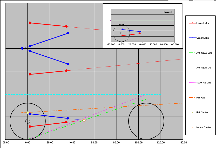
My virtual 4 link. Thanks to Dan Barcroft from the Internet for the calculator.
I began, simply enough, by purchasing a pre-made differential bracket made by Clayton. By bolting this to the differential, I was able to have a trustworthy starting point from which to take all my measurements for the upper links. Though this wasn’t necessary, and could have been made at home, it saved me a few hours of labor on what became a time crunched project..
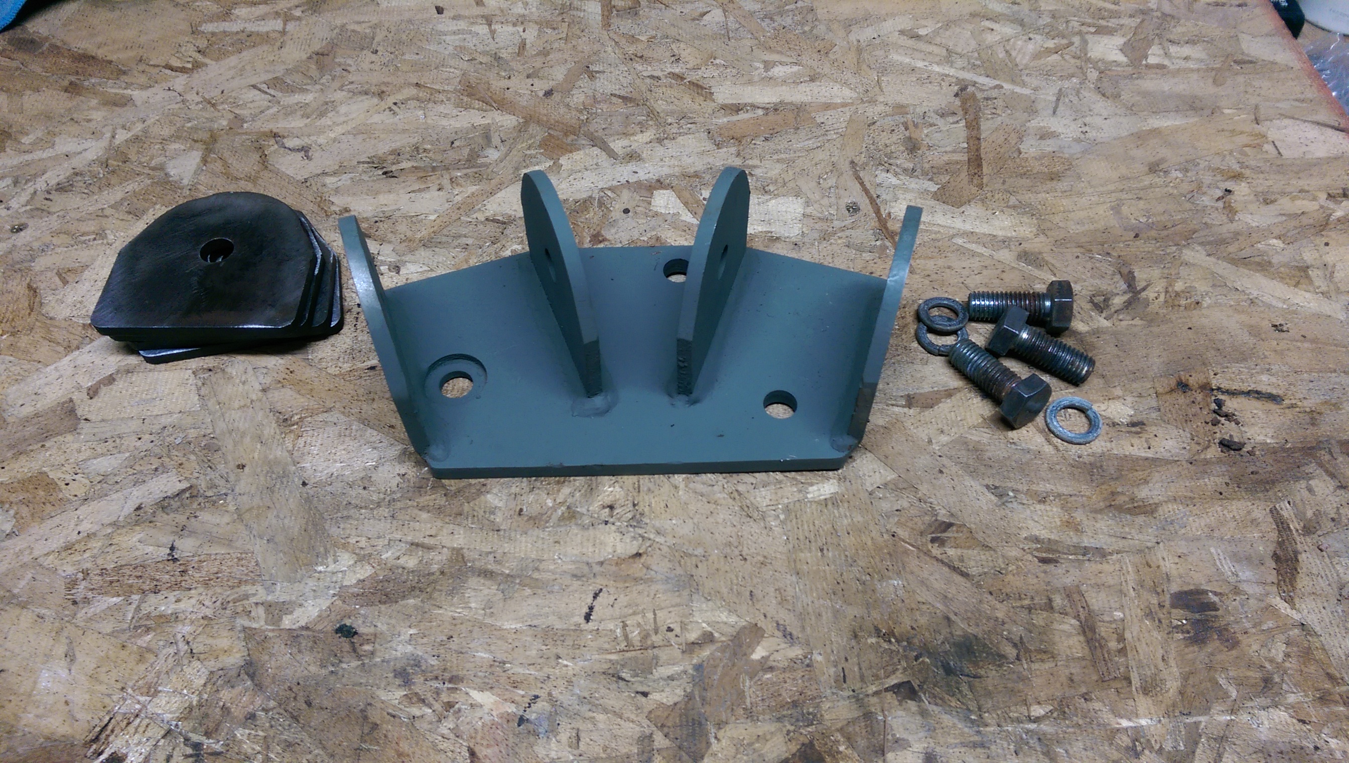
This bracket was the idea that started it all. And it saved hours of design time.
I may as well give a shout out to the guy who provided me this little gem…

Shipped it all the way from PA in just a few days, only for it to sit on my shelf for six months. Thanks all the same bud!
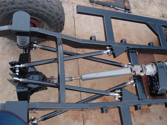
I spent a little while under a buddy’s WJ, which happened to have the Clayton 6″ lift on it, so I actually had a great reference during the project. After looking and measuring for a while, I decided that my best bet would be to pretty much copy exactly what they did.

The bracket that the rear links connect to on a Clayton kit…
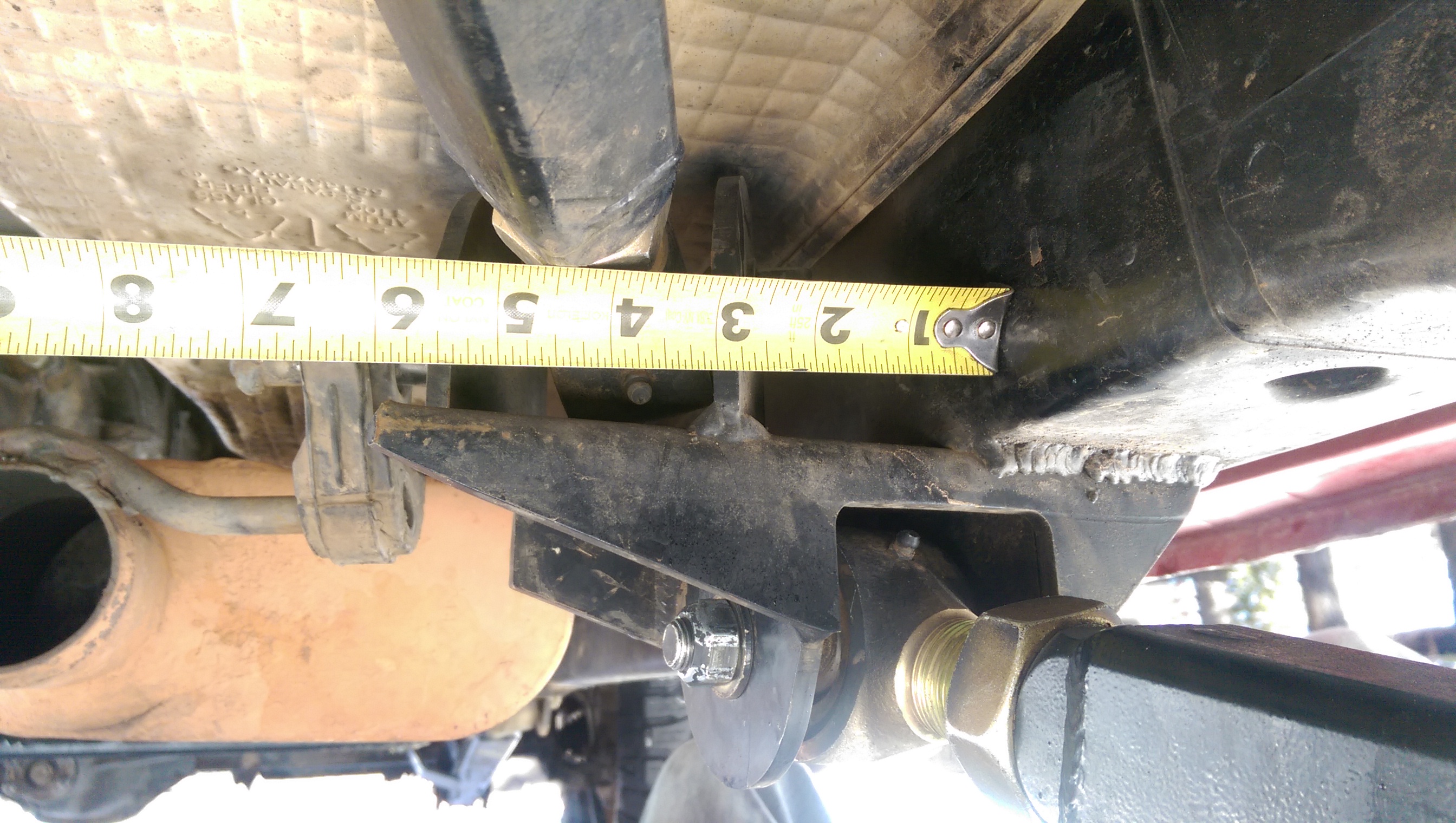
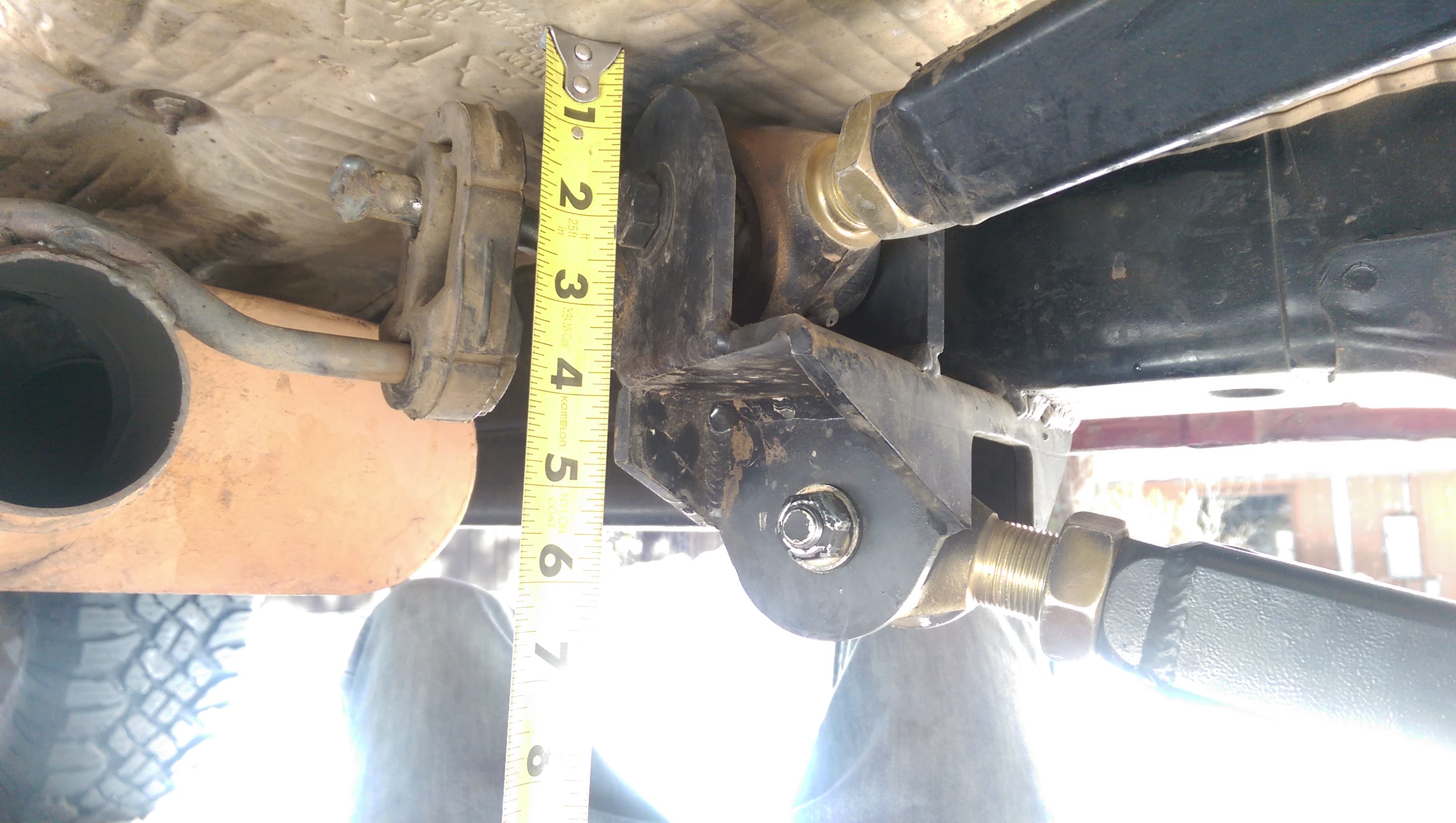
Some rough measurements…
The next thing to do was to replace the rubber (clevite) bushings in the RC lower links with real deal Currie Johnny Joints. This was optional, and should be pondered for a spell if you’re working on a daily driver. The clevite soaks up a LOT of the bumps in the road. Having Johnny Joints on all of the suspension will make you feel every bump in the road. Consider yourself informed…


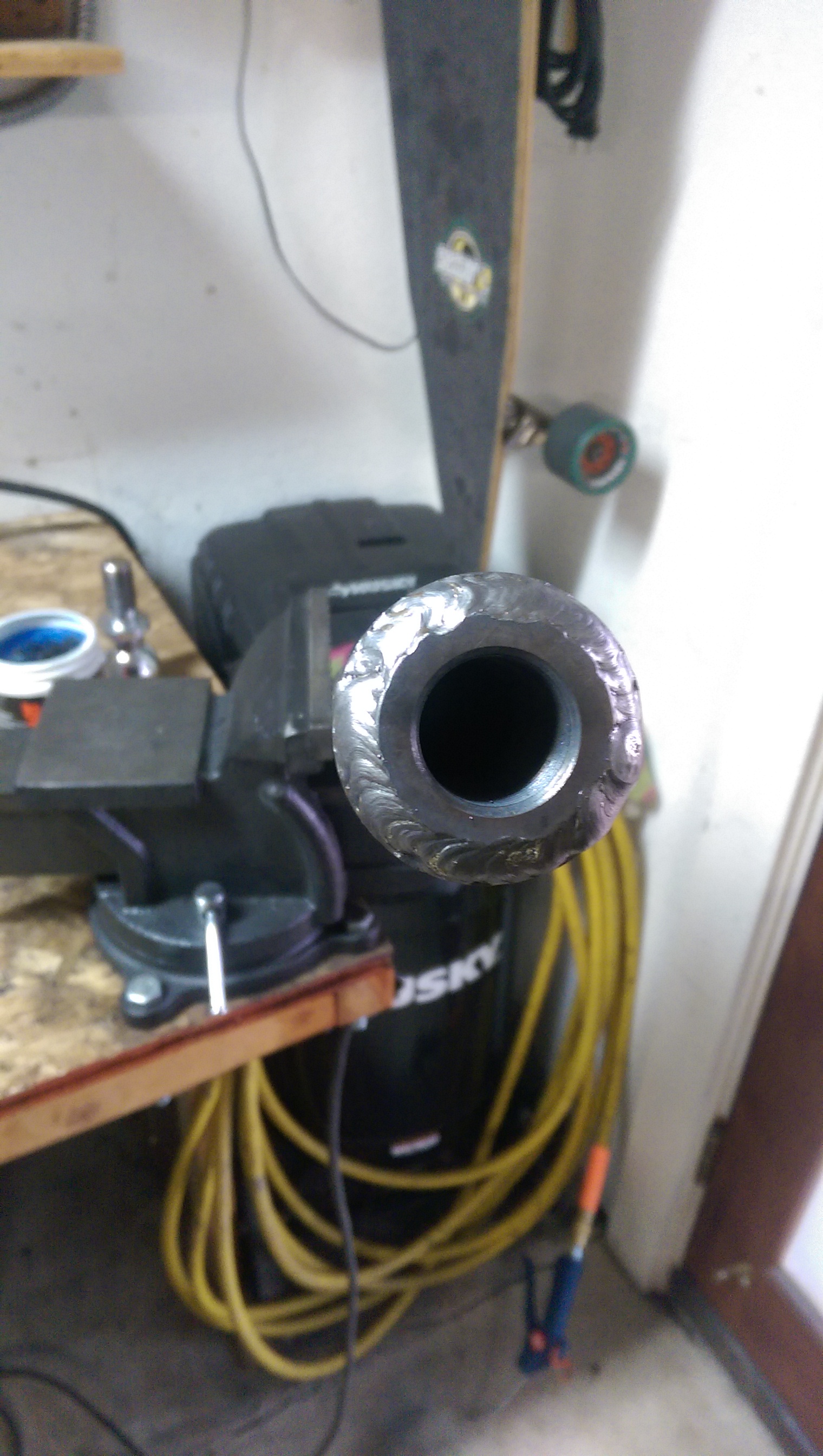
- In a bit of storyboard fashion, I first cut off the original housing that was designed for the clevite bushing. I then cleaned it up, notched it out to fit the new housing, and welded it together.
- Once that cooled, I put some fresh paint on it and installed the new Johnny Joint rod ends at the other end
- Those got installed and then it was on to the all new upper links.
The upper links play several roles in supporting the rear suspension. They’re the easiest to change to adjust your pinion (Differential/Driveshaft) angle, In my and other triangulated 4 link setups, they keep the axle lined up laterally to the vehicle, they’re often (combined with other things) what determine your anti-squat and roll axis. All of these variables have to be taken into account when locating the links, hence the calculator above. You can find it here.
With all of that out of the way, I started collecting materials:
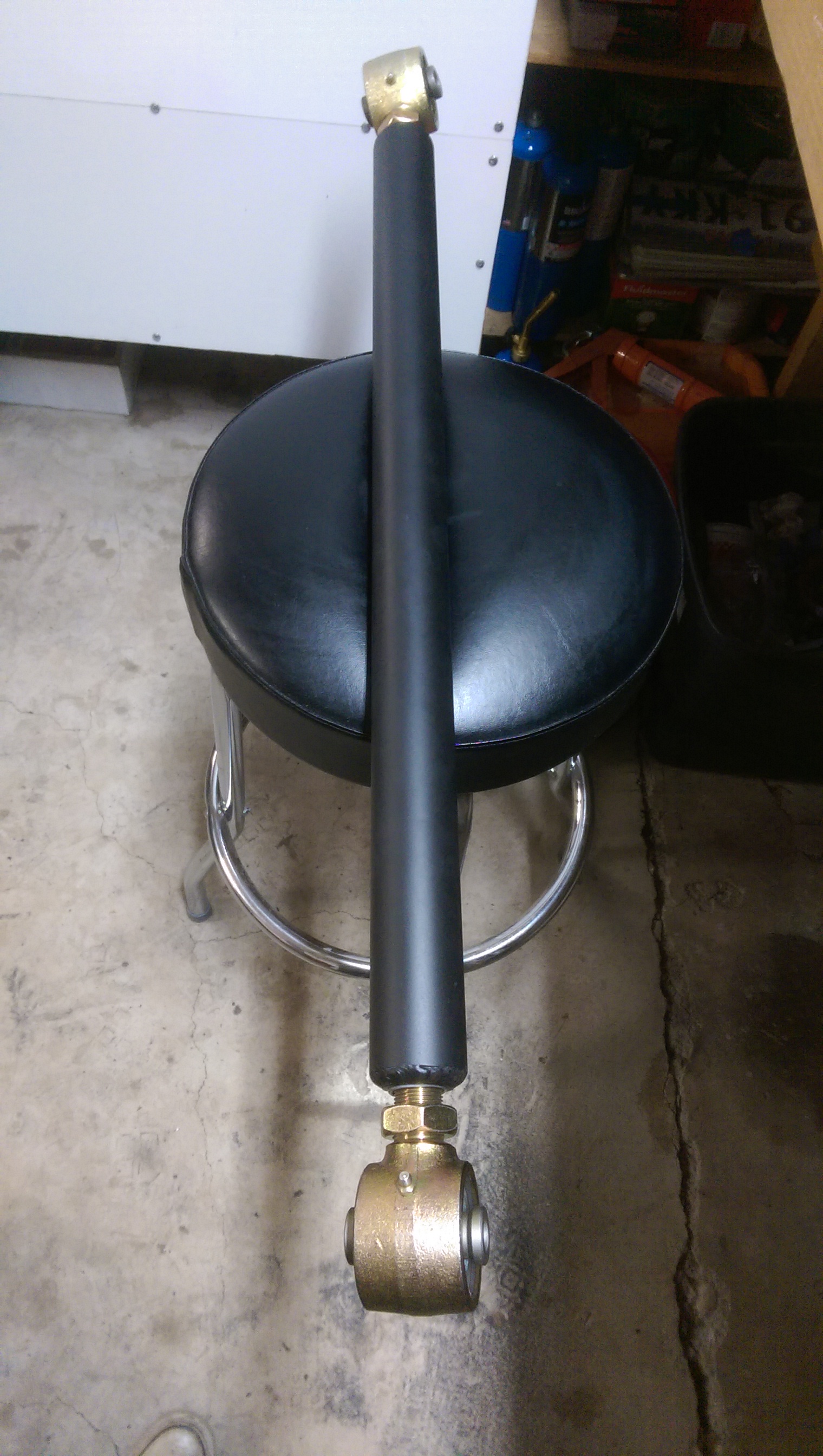
- 20 feet of 2″ DOM tubing ( to make sure I had extra in case I really screwed up)
- four 1″-14 weld in inserts (read: one inch – fourteen, in reference to the size and thread pitch of the bolt, or flex joint in this case..)
- four 2″ Johnny Joints with 1″-14 threaded rod end.
Here, I used a 2″ tow hitch ball (which, perfectly, had 1″-14 threads) as an anvil to hammer the inserts into the DOM tubing. Once there was approximately 1/4″ of insert left out (as above) I welded it all up. Then paint, and install the new Johnny Joints.
Next up: The Bracketry.
I’ll be honest. I straight up copied Clayton here (Thanks Clayton!). But it just ended up working so well with what I had, I’m certain I would have done the same thing even if I didn’t have the reference rig.
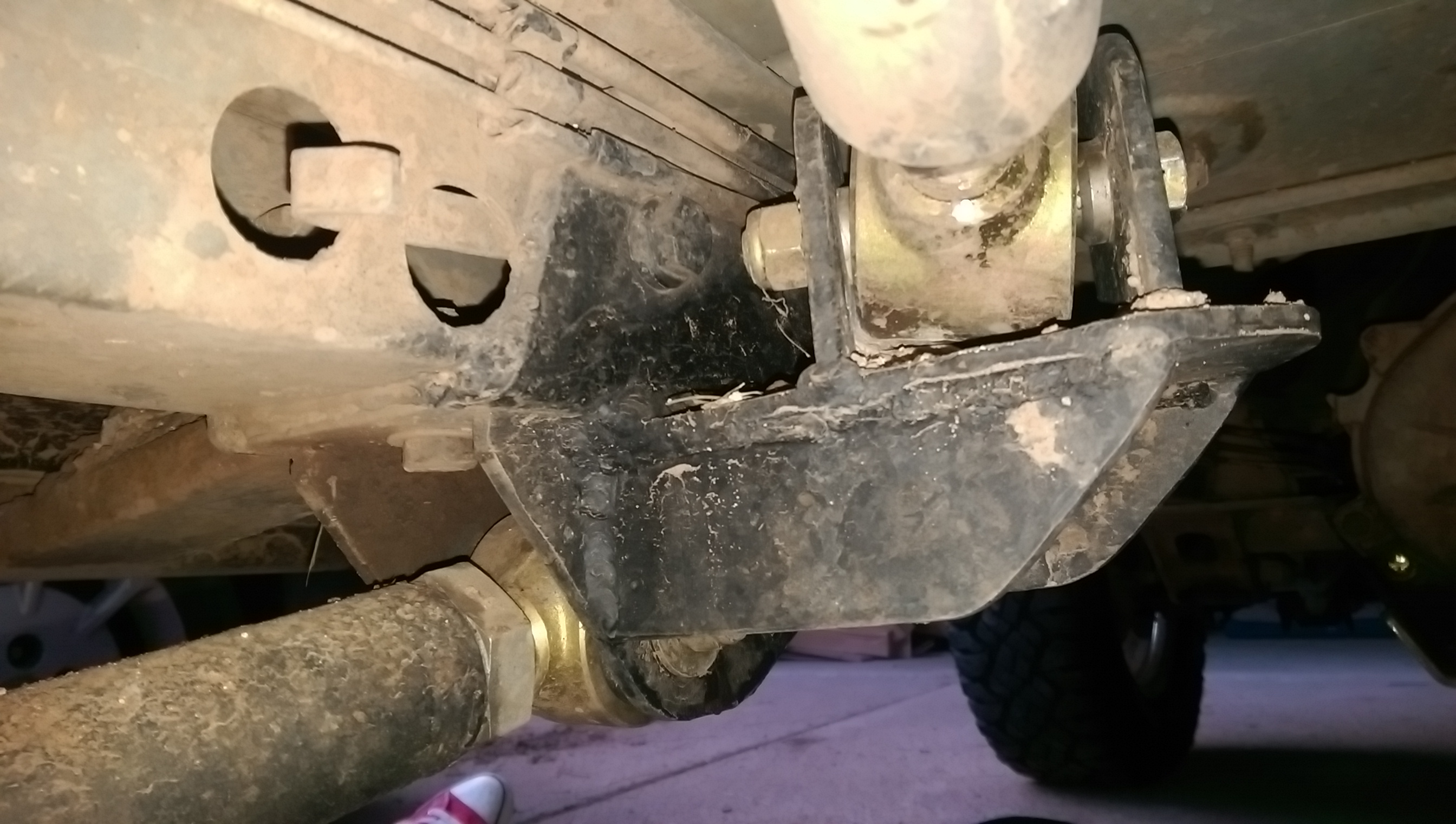
I ground the paint off of the brackets that are currently installed on my Jeep that keep the rear lower links in place. I just tacked some plate on it, and then cut and welded in some gussets. Then I pulled it apart, took it back to the bench and finished out the weld.

This is the plate and the gussets all welded up. A full bead on the outside (for looks) and three 1-1.5″ beads on the inside.
You can see where I had to start over a couple times above. I don’t have a dedicated circuit breaker for the welder yet, and 1/4″ is the max my welder can handle. This combination meant that I had to stop and start several times through the process. Future garage upgrade!

This is why you need gas when MIG welding. It causes bubbles. This was my first pass of the day, and I just hit the power switch and did work. Not my best moment…
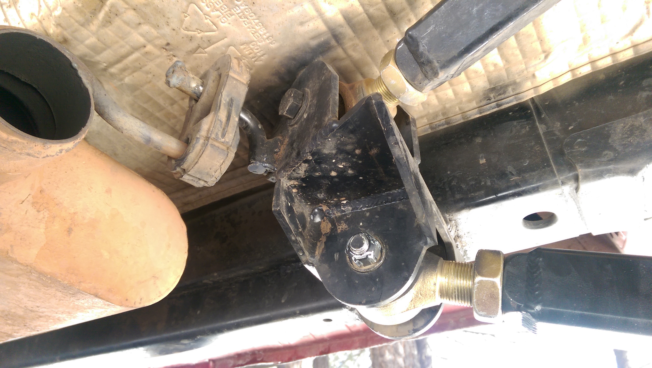
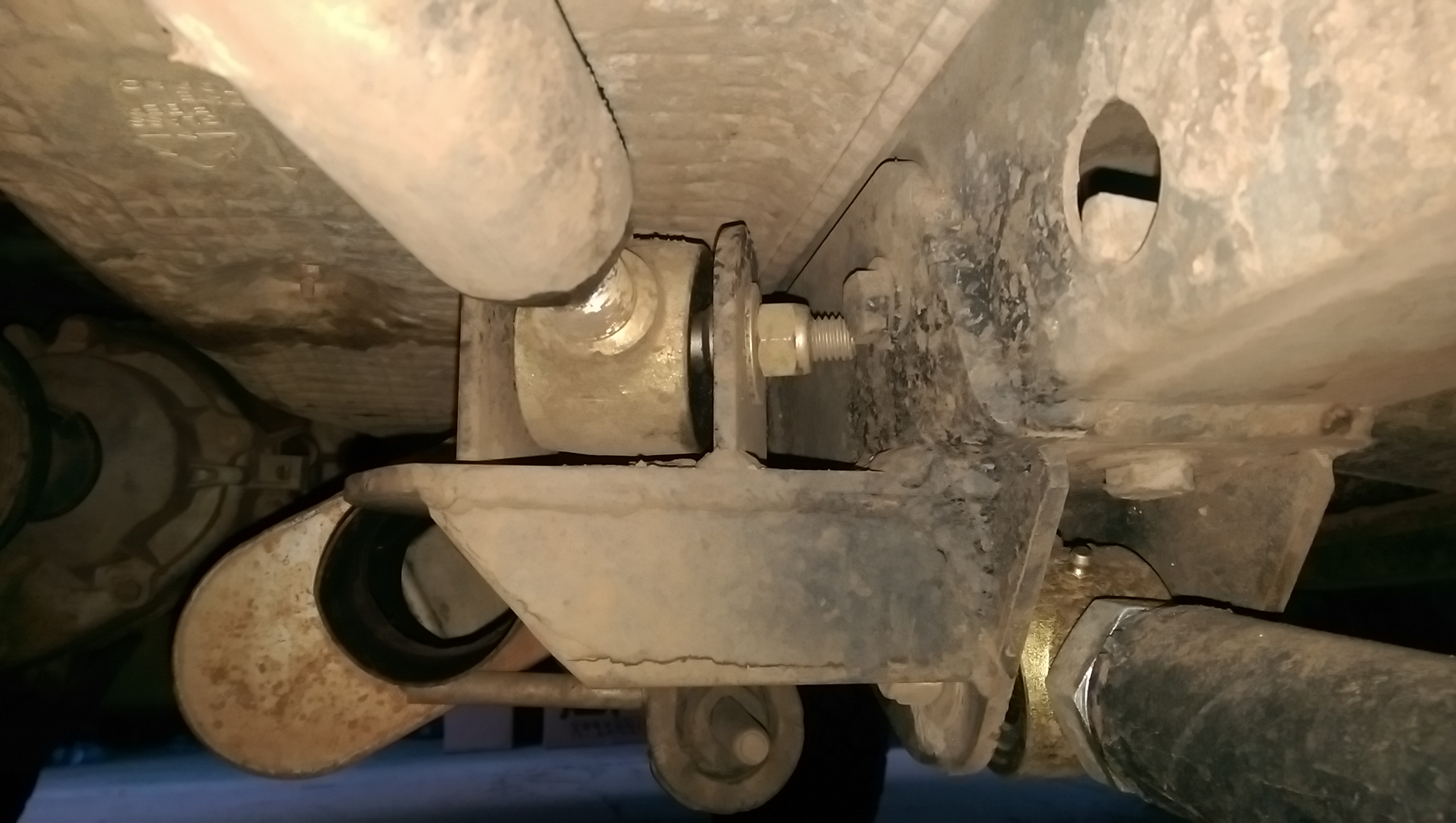
Up here you can see the bracket tacked to the Jeep, and the link with its tabs tacked to the bracket.
Instead of trying to math the entire project, I sometimes assembled things as I could, and let them naturally dictate where to get welded, like with the control arm above. I bolted the tabs to the joint, set the arm to it’s intended length, and then tacked it up. A couple minor alignments, and I’m confident that everything is aligned down to the thousandth. Saved me hours of time, and my brain from doing a lot of math.
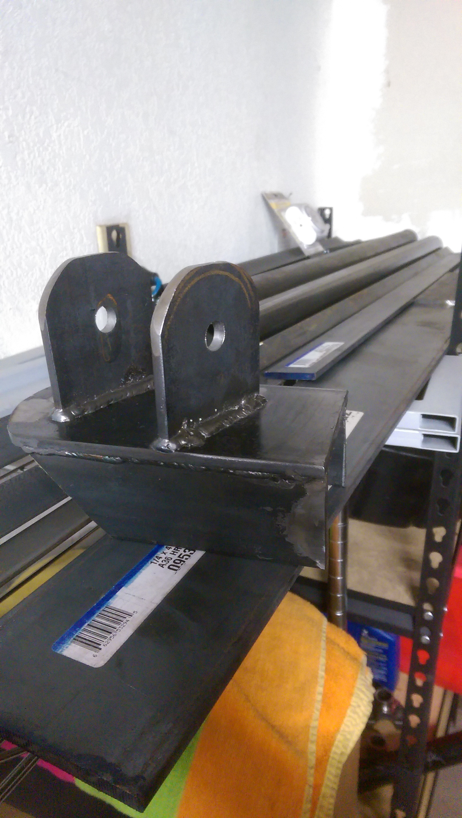
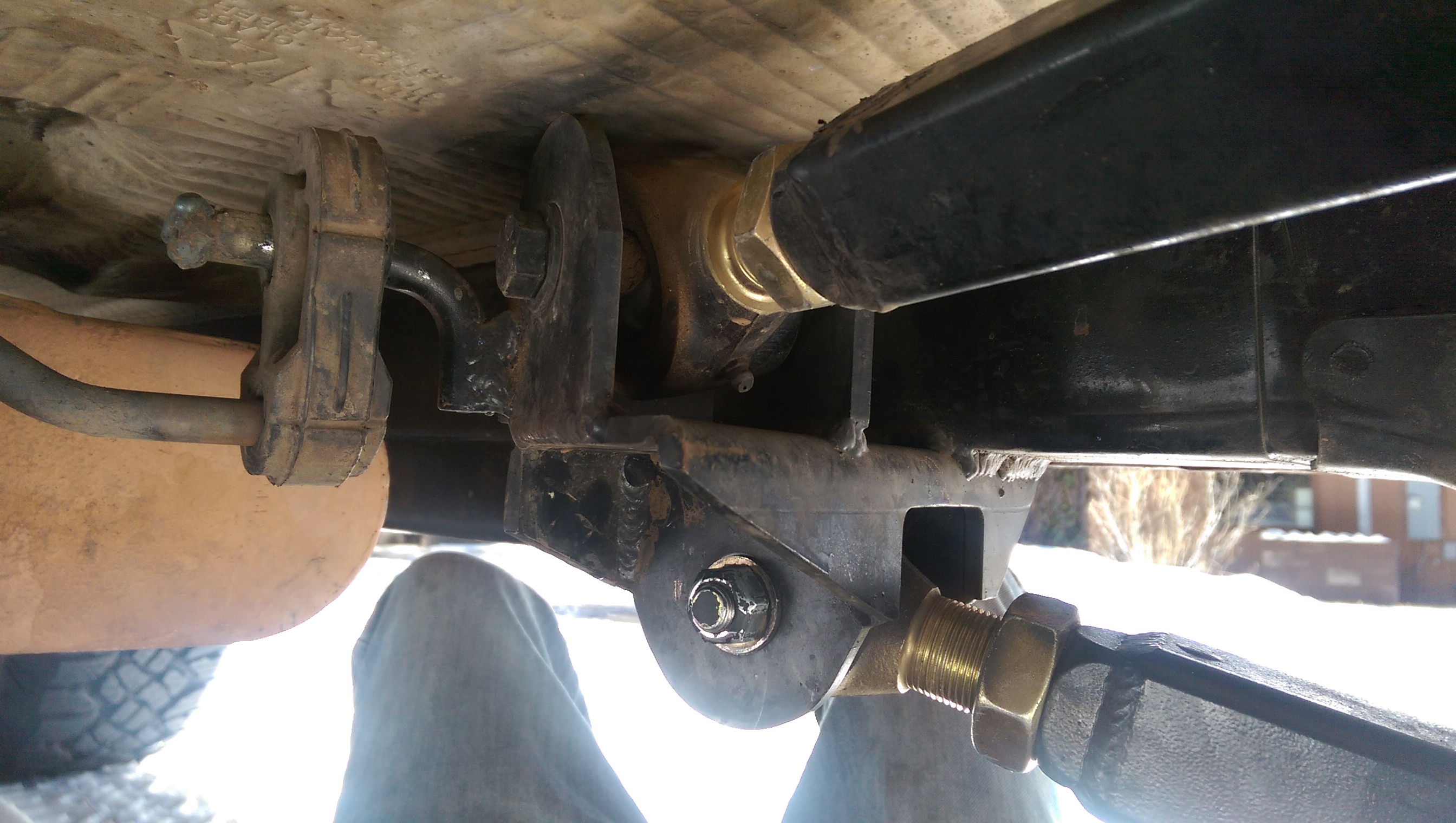
Here’s a fully completed bracket (passenger side, I think). I like this picture because it shows what I made, and what it came from. Before I got a hold of it, this was just bare flatbar. Now it’s part of my Jeep. Shit’s dope, yo.
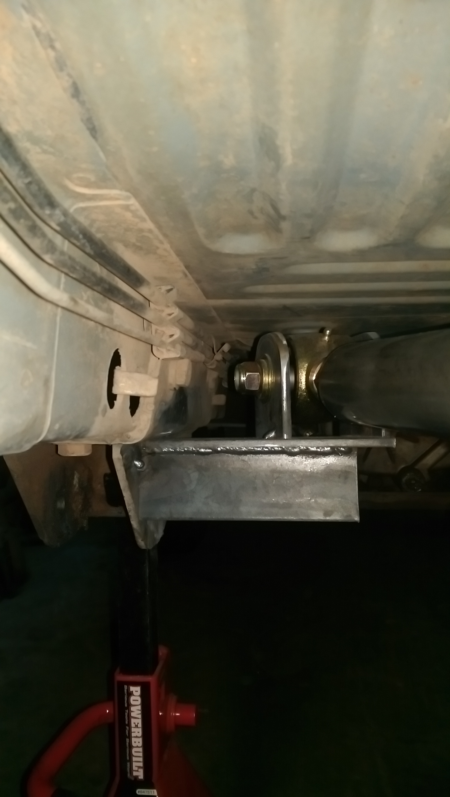
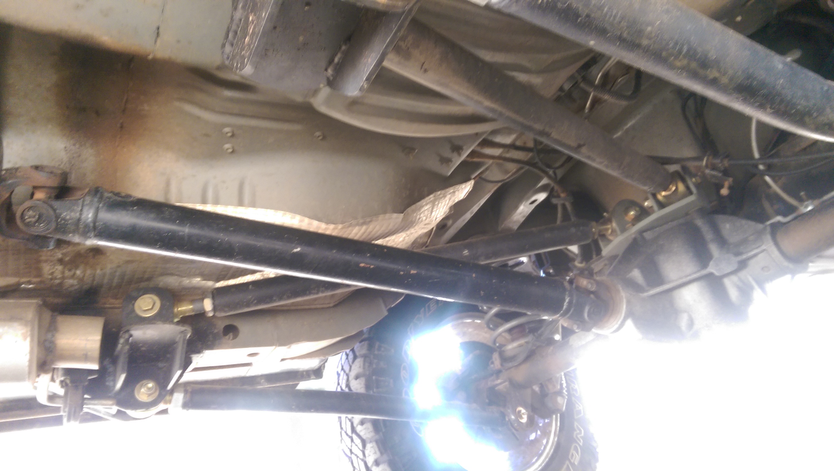
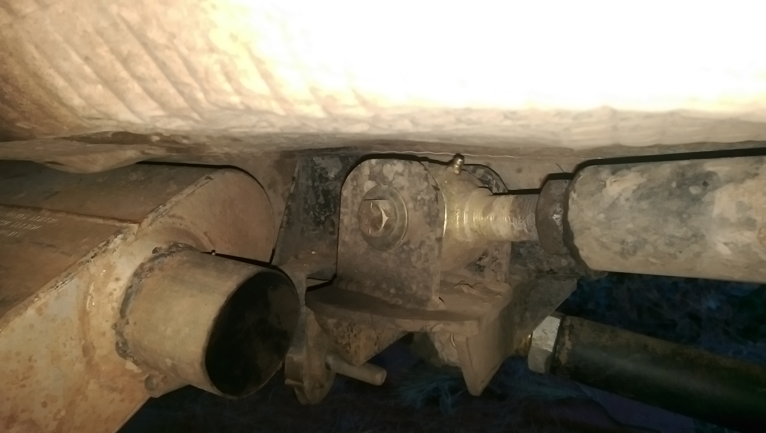
With the brackets welded up, they were tacked back into the Jeep again, but for the last time. After getting them aligned and tacked in place, I seam welded them to the Jeep for forever. Not the prettiest welds, but they’ll be strong, and that’s the important part.
Once that was done, it was a fairly typical affair of bolting everything back together, then tightening the control arms down once the jeep was sitting on tires again.
I still have a few things that need to get done before I call this project complete, but none of them are affecting driveability, so I’ll get to them when I can. Here’s the list, as much to help me remember, as it is for your entertainment.
- limit straps (need to wait until after the new springs)
- Spring retainers (built, but waiting for new springs) These will also act as bumpstops.
- find a way to extend the parking brake lines. Other than the shocks, this is what’s limiting downtravel right now.
- look into moving upper shock mount. (Hold my beer, I’m gonna try something)
- install new spring isolators. They’re here, but I may as well wait for the new springs.

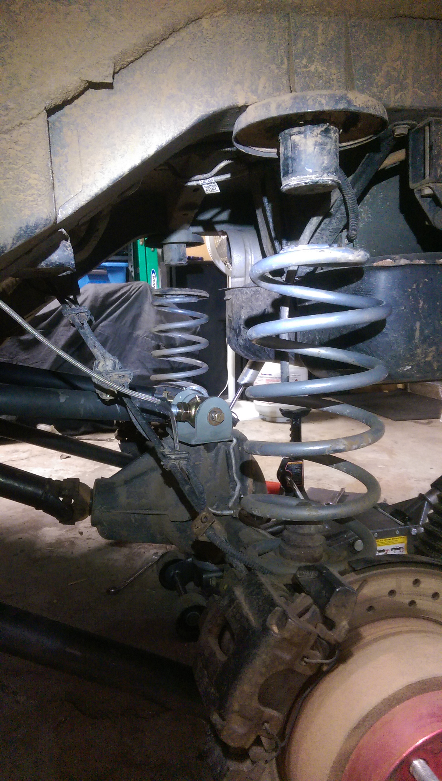
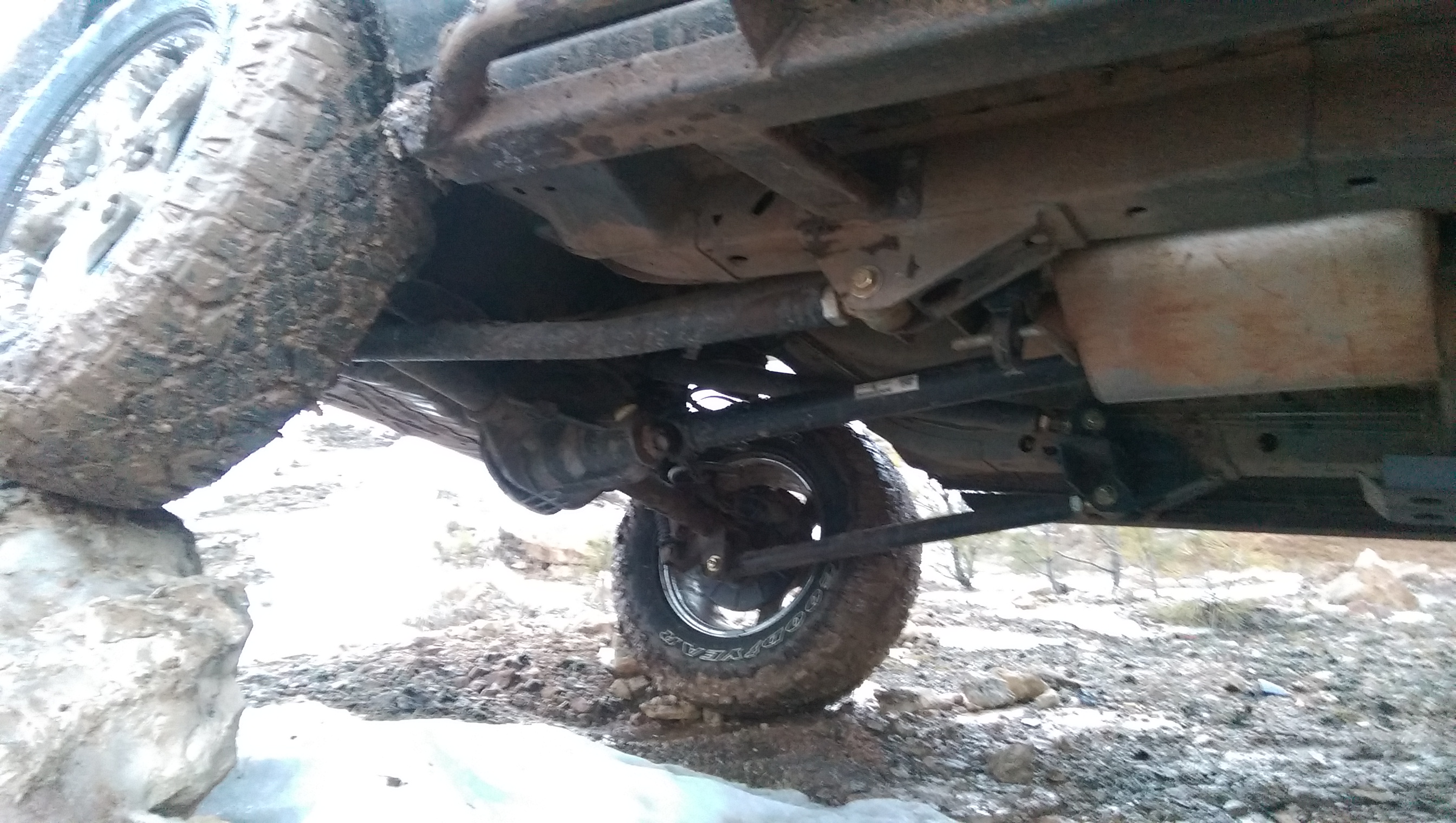
So droop! Much wow!
Remember when I said I screwed up a few times? Well, scroll back up to those pictures of my “reference rig”. The ones with the measuring tape. See how it has a short exhaust to make room for the 4 link? Yeah, I completely forgot about this necessary step until I was literally welding things into the jeep. I don’t know how I worked around that muffler for two days without remembering it… At any rate, a buddy of mine came through with a clutch 40 series Flowmaster, which he most awesomely donated to the project that very night (my life is dope and I have dope friends). I expected it to sound awful. It doesn’t. Remember when I said my life is dope? That muffler sounds perfect.
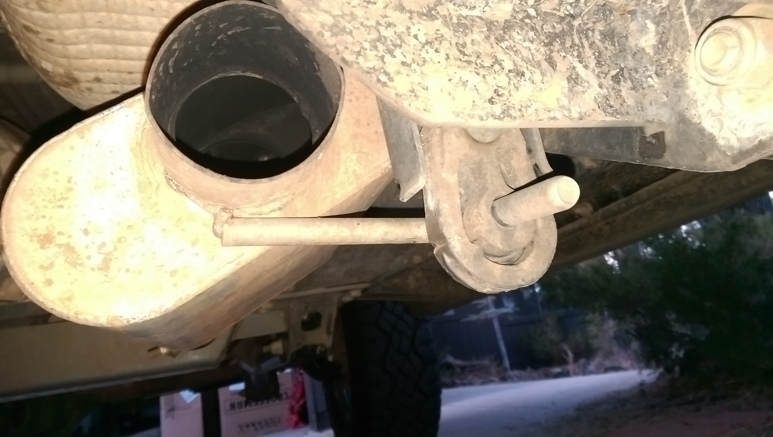
Thanks Zeep!
Other things I screwed up really well:
- When welding the tabs to the brackets, somehow I did two passenger sides. This is a feat, because it means that I measured it, placed it, re measured it, tacked it in, put the control arm on it, tacked those tabs on, took the bracket off of the jeep, and then welded it completely. All without realizing I was making the wrong side. I’m not even really mad at this, just really confused about how I did it. And yea, it was fully welded when I realized it… [-30hp] [+3 hours labor time] for my gamer nerds out there.
- I didn’t remember to reset the pinion angle of the axle before tacking the tabs onto the brackets the first time, which, if not caught, would have resulted in not being able to set the angle correctly, which, at that amount of angle would have destroyed the rear diff (read: Tango Uniform). [-10hp] [+1 hour labor time]
- I hammered directly on the threads to get the inserts into the control arm links the first time. Hence that fancy tow ball, haha… 😦 [-50hp] [+5 hours labor time] [-1 full day of progress]
- I forgot to turn on the welding gas more than just once… [-1hp] [+1 Red Foreman meme]

All in all, I’m really proud of the whole thing. It was my first go at a project this ambitious, and it turned out baller AF. I’m hoping to do a similar project for the front control arms some time this summer.
So how does the 4 link perform?

It do aight.
